TIMING COUNTER TEST page
Measurements of a first timing counter prototype
The prototype
The prototype was built with BICRON BC-404 plastic scintillator
( BICRON web site):
its dimensions
are 100 cm x 5 cm x 1 cm. The scintillator is wrapped in an aluminized
foil and light guides are glued at both ends.
The scintillator is read by two PMTs PHILIPS XP2020/UR which have a FWHM
transit time spread of 470 ps.
The TEST system: CORTES
The scintillator bar was tested by means of the COsmic Ray TESt facility
(assembled by our group) which is sketched below and is composed
of two sets of 4 planes of MicroStrip Gas Chambers (MSGC) providing
very precisely the tracks parameters of the crossing muons. The dimensions
of each chamber are 10 cm x 10 cm. Four chambers (y-chambers) have
their strips oriented along the y-axis defined in the sketch below, while
in the other four (u-chambers) the strips are oriented at 5.7 degrees relative
to the y-axis. The distance between two adjacent chambers is 4 cm while
the gap between the two chambers sets (where the detectors to be studied
are put) is 20 cm. The CORTES resolution on the track intersection
with the plane of our prototype is less than 1 mm
in the y direction and about 60 microns in the transverse direction.
Two 12 cm x 12 cm plastic scintillators C1 and C2 (BICRON BC-408) provide
the coincidence for the trigger, while the two smaller scintillators
T3 and T4 (BC-404, 5 cm x 5 cm each) are used as a good time reference.
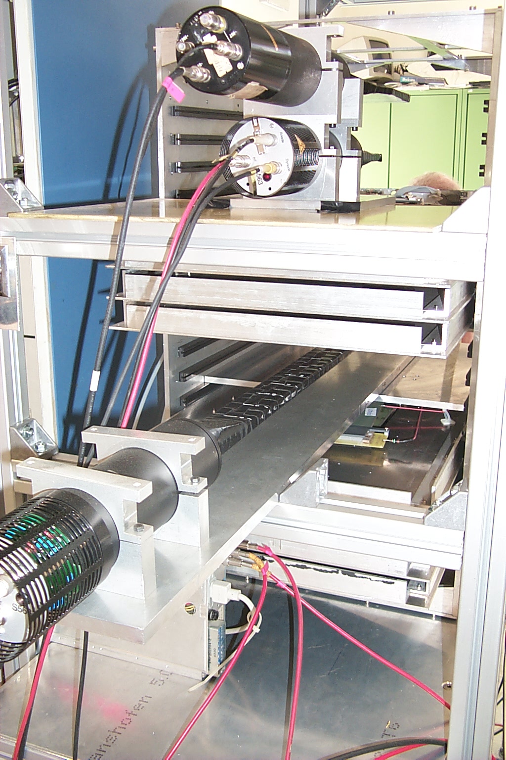
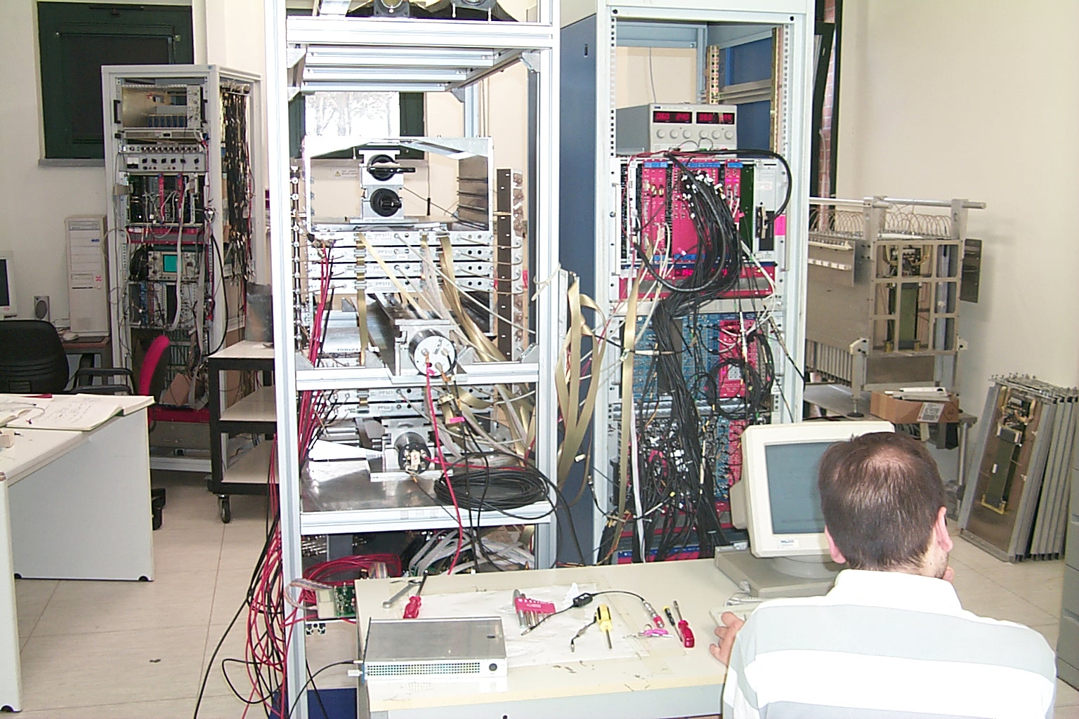
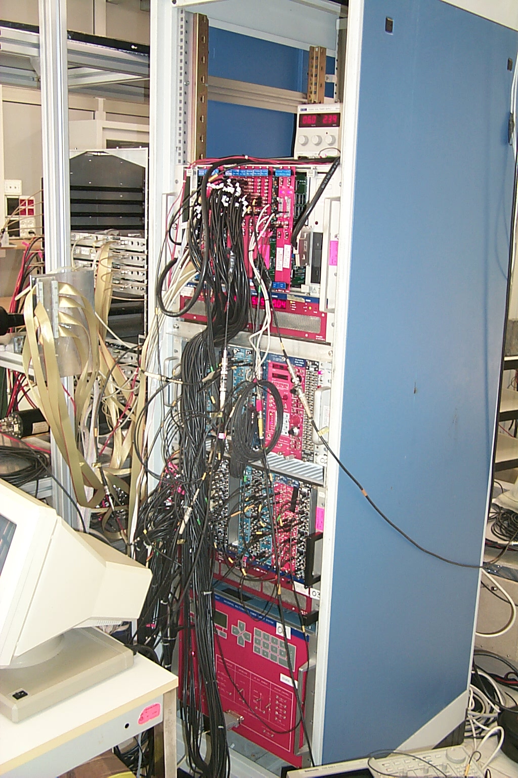
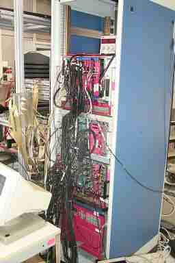
 Here are a couple of photographs of the set-up described above (Click
on the images to see enlarged photos).
Here are a couple of photographs of the set-up described above (Click
on the images to see enlarged photos).
Electronics
Each PMT anode signals is discriminated (NIM LeCroy 623B)
and then sent to a VME TDC (CAEN V488AS: 16 ps least count). The
last dynode of the PMTs is used to measure the pulse charge via a CAEN
ADC V465. The TDC was used in common-stop operation mode with the
common stop provided by the delayed C1-C2 coincidence.
Analysis and results
TDC data are corrected for the measured muon position along the counter and
for the charge-dependence that give rise to the time-walk effect.
An example of the measurement of the TDC-ADC correlation is given
in the following picture.
 We measure and take into account the variations of the light speed along
the counter.The distribution of T1-T2 for muons at the center of the detector
is shown in the following picture.
We measure and take into account the variations of the light speed along
the counter.The distribution of T1-T2 for muons at the center of the detector
is shown in the following picture.
 In the next picture we show the time resolutions (after subtracting the reference
counters resolution) for the two sides
of the counter, their weighted average and the T1-T2 resolution, as a function
of the muons passage along the counter.
In the next picture we show the time resolutions (after subtracting the reference
counters resolution) for the two sides
of the counter, their weighted average and the T1-T2 resolution, as a function
of the muons passage along the counter.
 These resolutions are in agreeement with previous results when the different
number of photo-electrons is taken into account.
A new prototype read by Hamamatsu fine mesh PMTs is currently under test.
These resolutions are in agreeement with previous results when the different
number of photo-electrons is taken into account.
A new prototype read by Hamamatsu fine mesh PMTs is currently under test.
 MEG Pisa,
May 25, 2001
MEG Pisa,
May 25, 2001